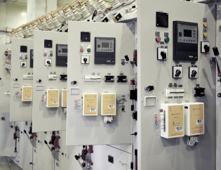
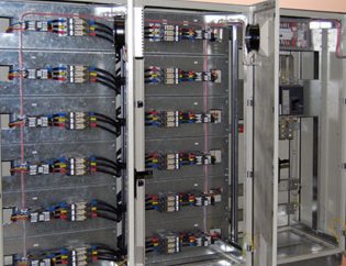
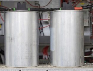
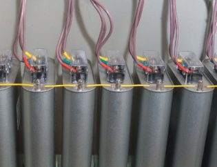
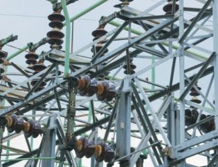
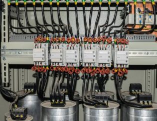
In order to maintain a reasonable ratio between the actual power used by the load and the total power of the electric system, this reactive power must be correctly adjusted. In this case, total power is the product of reactive and active power. The electrical pf refers to this ratio (power factor). If an electric system’s pf is low, the load on the transmission, alternators, and transformers that are linked to the system will increase to provide the necessary active power. Reactive power adjustment will thus become crucial. Therefore, a capacitor bank is typically used for this.
Here, you’ll learn all types of capacitor banks and their calculation. So, keep reading further.
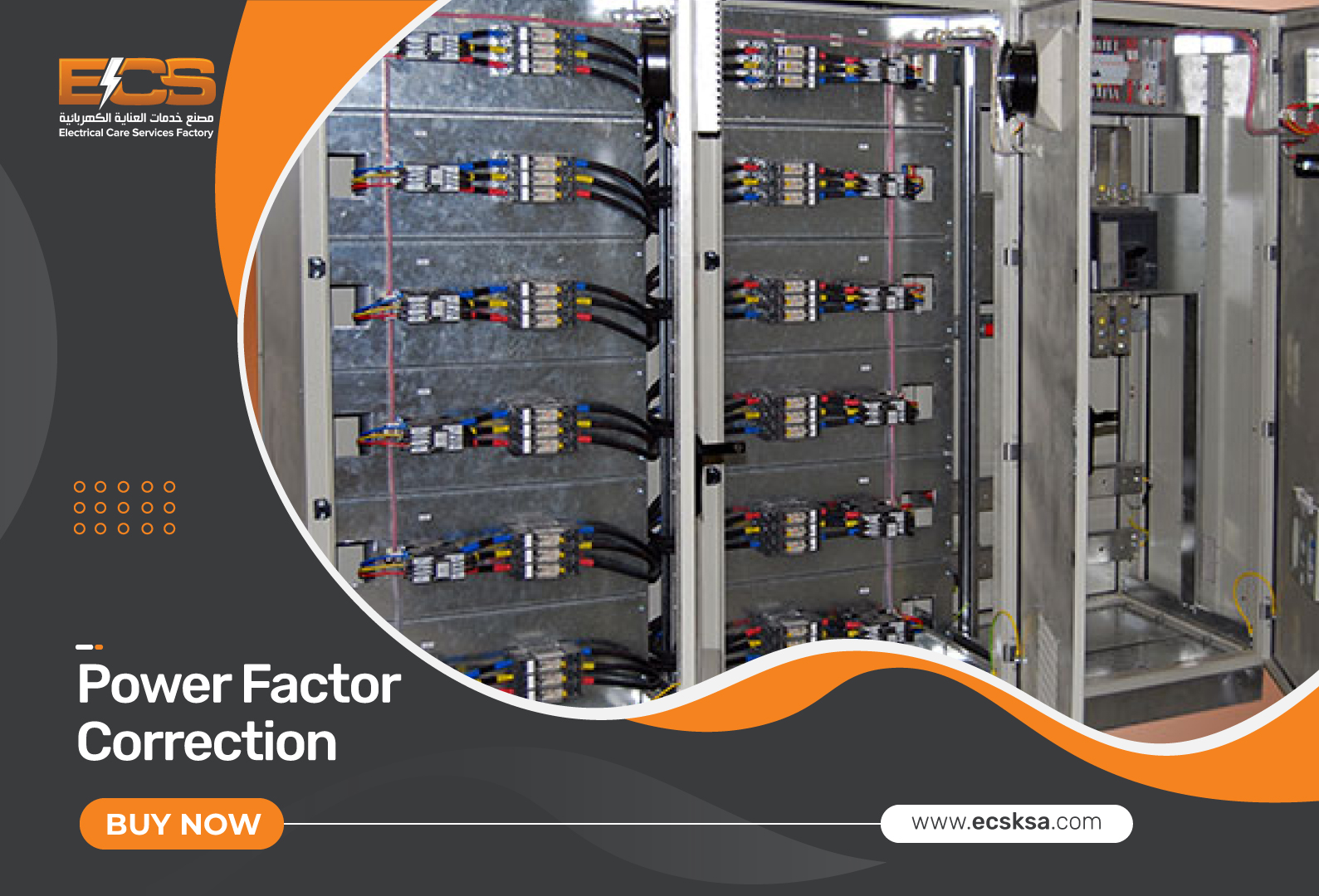 What is a Capacitor Bank?
When a number of capacitors are connected in series or parallel and have the same rating, the arrangement is referred to as a capacitor bank. Electrical energy is typically stored in a single capacitor. Therefore, increasing the number of capacitors in a bank will increase the amount of energy that can be stored in a single device. Below is a basic symbol or diagram for a capacitor bank.
It is used in a substation to improve the power factor and compensate for reactive power. A substation’s capacitor bank installation requires taking certain requirements into account. Voltage rating, temperature rating, KVAR rating, and basic instruction range are the parameters for capacitor banks.
Types of Capacitor Banks
The unit of a capacitor bank is typically referred to as a capacitor unit. These units can be produced in a manner similar to one-phase units. To create a complete three-phase capacitor bank, these units are mostly coupled in the form of a star/delta connection. The most common capacitor units currently on the market are of the 1-phase kind, whereas 3-phase capacitor units are rarely produced. Three different kinds of capacitor banks are available; they are explained below.
- Internally Fused
Within a specific layout, an internally fused can be designed. Different elements are connected in series and parallel according to their rating. Through a fuse unit, each capacitor element can be protected independently. As the name implies, both the fuse units and the capacitor elements are grouped inside the same shell. Every capacitor element in this kind of bank has a very small size that falls within the ratings.
Therefore, if any of the capacitor’s components fail, the bank’s operations won’t be affected. Even if one or more capacitor parts are damaged, this type of capacitor bank can still function properly.
The key benefits of an internally fused type include its ease of installation and maintenance. The drawback of an internally fused is that the entire bank must be replaced if many capacitor elements fail. Therefore, it is not possible to replace a single unit.
- Externally Fused
The fuse unit for each capacitor unit is provided externally in an externally fused form. The fuse unit will be harmed if any capacitor unit malfunctions. When the fuse unit separates the damaged capacitor unit, the bank will continue to operate without interruption.
For each phase of the bank, this type allows for the parallel connecting of capacitor units. If one component fails, the performance of the entire bank won’t be significantly impacted. When one capacitor unit is missing from a single phase, that phase’s capacitance will be lower than the capacitance of the other two phases.
High voltage in the bank’s final two phases will be impacted by this. Once the fuse unit blows, it is possible to identify a defective unit of this type through visual inspection. The usual capacitor unit rating lies between 50 KVAR and 40 KVAR.
The fundamental drawback of this bank is that even when all of the units are functioning well, an unbalance cannot be identified once any fuse unit fails.
- Fuseless
A capacitor string can be created by connecting numerous fuse units in series in a fuseless form. Each phase has its own capacitor bank that is created by joining these threads in parallel. Following that, a three-phase bank is created by joining three-phase banks that are connected to one another via a star/delta connection.
The capacitor strings are not secured by a system of internal or external fuses. Because there are multiple other capacitors connected in series through this path, there is no change in the flow of current if any one of the string units fails in this type of system due to a short circuit or another defect.
When the string unit’s internal short circuit effect is minimal, the capacitor bank can be built up to delay replacing the defective unit. This is the major reason why, when a unit becomes defective, it is not required to immediately replace it with a new one from the bank’s system.
Capacitor Bank’s Connections
The capacitor bank can be connected in two different methods, including star and delta, but the delta is more frequently utilized. As a result, it’s unclear which connection would be best for a bank. We will now talk about these two connections, their advantages, and their disadvantages. As a 3-phase system uses a 3-phase capacitor bank for power factor correction, which may be coupled in a star or delta pattern, this is a major application.
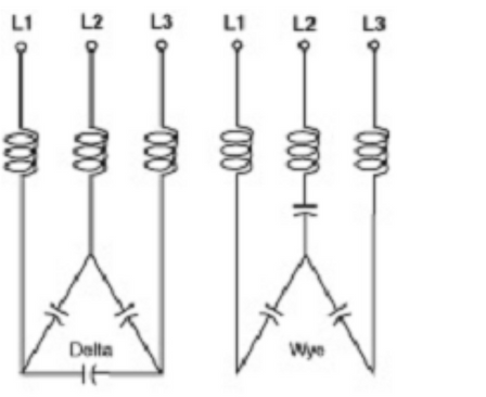
Capacitor Bank in Delta Connection
These banks are utilized for less than average voltage when they are utilized in delta connections. The capacitor bank in a delta connection can be used for high voltage, but it is occasionally not possible since every capacitor receives the full phase voltage in a delta connection, whereas with a star-type connection, the applied phase voltage is lower.
Thus, the capacitor’s voltage rating must be high if we use a delta connection at a high voltage. As a result, producing high-voltage capacitors is sometimes both expensive and impractical.
Advantages
- Kilovolt-Ampere Reactive (KVAR), which the capacitor produces, is proportional to the square of the applied voltage. Therefore, a higher voltage corresponds to a higher KVAR. As a result, the capacitor in this connection will offer higher KVAR than the bank linked in a star connection, since the applied voltage in a star connection is lower than in a delta connection.
- By allowing the harmonic current to travel through the capacitor bank in this connection, the harmonic influence on an electrical system is reduced. Every stage of the electrical system receives a balanced capacitance when the bank is connected in a delta connection, which also maintains a balanced voltage.
- If a capacitor cell in a single phase of the bank fails, the voltage beyond all phases stays the same, and KVAR falls.
Disadvantages
- The biggest disadvantage of a capacitor bank in a delta connection is the pressure of voltage across each capacitor, which shortens its lifespan and prevents it from being used in high-voltage applications.
Capacitor Bank in Star Connection
The star connection-based kind is primarily utilized in medium- to high-voltage applications. The pressure of voltage beyond the capacitors is lower even in applications requiring the maximum voltage in this style of connection because the voltage beyond each capacitor is lower than the voltage of the phase.
Advantages
- It’s an easy connection.
- Every capacitor has a low voltage pressure across it, which lengthens its lifespan.
Disadvantages
- Because the voltage across the capacitor is lower, the star-connected type offers less KVAR than the delta-connected kind.
- The harmonic current in an electrical system cannot be circulated by a star-connected type.
- Ungrounded star-connected types are unable to maintain balance voltages or supply balance capacitance.
- The electrical system experiences an imbalanced voltage if a capacitor cell in one phase fails.
Capacitor Bank Calculation
The true power in MW/W is required if we wish to measure the value in VAR or MVAR. For instance, if the value is expressed in kW, you may easily convert it to kVAR. The same is true for MW & W. The real power, P, is equal to the needed reactive power, Q(kVR) (kW). Below is a formula for the capacitor bank calculator.
Required Reactive Power (kVAR) = P(kW) * tan (cos-1(PF1) – cos-1(PF2))
Required Reactive Power (VAR) = P(W) * tan (cos-1(PF1) – cos-1(PF2))
Required Reactive Power (MVAR) = P(MW) * tan (cos-1(PF1) – cos-1(PF2))
Read more: A complete guide on the capacitor bank calculations
Conclusion
Now, you know all types of capacitor banks and their connection types. So, use this knowledge to improve the efficiency of your electrical distribution systems.
Remember, a delta connection capacitor bank works best for low and medium voltages.
On the other hand, a star-connected capacitor bank is good for high voltages.
Do you have a question in your mind? If so, make sure to fill out the form below!


