The power factor and apparent power are connected. The following can be taken into consideration if you wish to learn more about power factor and power factor adjustment. We will also talk about how to use power factor, why power factor matters, how to use a power factor correction capacitor, and how to increase power factor. In addition, we’ll talk about the formula for power factor correction.
The relationship between apparent and actual power is known as the power factor. Based on the correlation between real and apparent power, we might have weak and strong power factors. The cost of electricity will increase if the power factor is low. The power factor correction enters at this point.
Let’s dive deep into power factor correction.
What is Power Factor?
Power factor is a factor in power quality, which is necessary for effective equipment operation.
An electrical installation’s power factor is a gauge of how well incoming electricity is used. The ratio of apparent to active power occurs when:
- Active Power (P) is the amount of energy required to do practical tasks like turning a lathe, lighting a room, or pumping water, and is measured in Watts or KiloWatts (kW).
- Reactive Power (Q) is a measurement of the energy that is stored but is reflected to the source and is expressed in var or Kilovar (kVAR).
- The vector total of active and reactive power, measured in Volt Amperes or KiloVolt Amperes, is known as apparent power (S) (kVA)
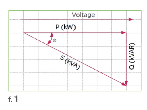
When the power factor is low (less than 95%), more current is needed to accomplish the same amount of work.
What is Power Factor Correction?
Enhancing power factor and hence power quality is the goal of power factor correction (PFC). It promotes energy efficiency, lowers power prices, and lessens the demand on the electrical distribution system. Additionally, it lessens the possibility of device instability and failure.
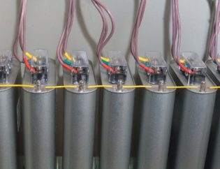
The connection of capacitors, which locally provide reactive energy in opposition to the energy absorbed by loads like motors, allows for power factor correction. Reducing the needless flow of current through the network raises the power factor, starting at the point where the reactive power source is attached.
Why Do We Need Power Factor Correction?
To manage our energy costs, we should all be aware of power factor and power factor correction. You can lower the electricity bill by carrying out a few straightforward actions. It will also ultimately save you a lot of money. You may have concluded from the foregoing that reactive power costs more. However, this electricity is not directly used by your devices. Therefore, there is no benefit to paying that additional fee. You can save that money and put it toward other things if the power factor results are better. A strong power factor will also lengthen the lifespan of your electrical equipment. There are numerous advantages, but you must know how to do it correctly in order to reap all of them.
The majority of power providers will bill you in kW. (for the base load). Additionally, the maximum demand tariff will be charged. The power factor will be improved when the maximum demand tariff is expressed in kVA. Additionally, it will reduce your installation’s kVA. Energy costs will be lower as a result, as will the maximum demand tariff. The capacitor installation will provide long-term advantages.
How to Determine Power Factor Correction — Power Factor Correction Formula?
We use a voltmeter and an ammeter, respectively, to measure the source voltage and current drawn for the purpose of calculating the power factor. The active power is measured using a watt meter.

Power Factor (P) = VIcosφ watt
The reactive power can be calculated using the following formula.
Q = VIsinφ VAR
Using the following formula, a capacitor’s reactive power can be determined:

Step-by-Step Process of Selecting Power Factor Correction Equipment
Step 1: Determination of the required reactive power
To increase the power factor (cos) and decrease apparent power, it is necessary to calculate the amount of reactive power (Qc (kvar)) that must be installed.
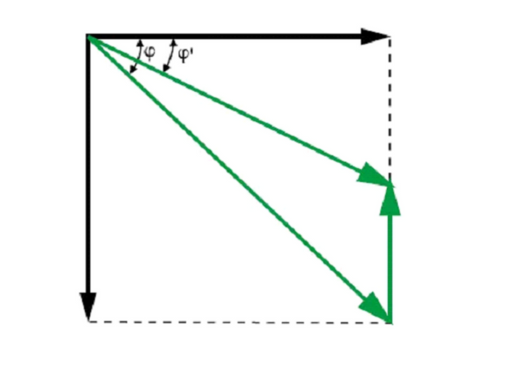
The formula Qc = P (tan – tan ‘), which is inferred from the diagram, can be used to calculate Qc.
- Qc is the capacitor bank’s power in kVAr
- P is the active power in kW
- tan φ is equal to tangent of phase shift angle before compensation
- tan φ’ is equal to tangent of phase shift angle after compensation
- You can get φ and tan φ from your bill or can measure directly.
Step 2: Choosing the compensation mode
Low-voltage capacitors can be placed in a low-voltage system centrally (in a single location for the entire installation), by sector (section by section), at the load level, or in a mix of the latter two locations.
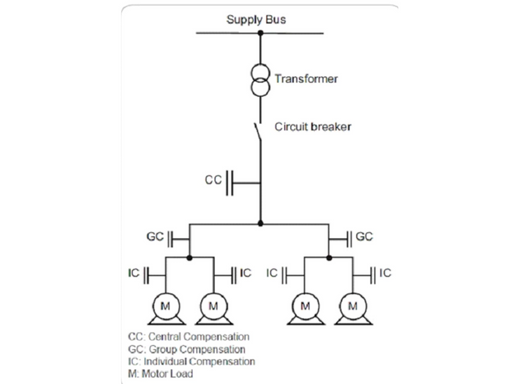
The optimal compensation, in theory, is applied at the point of consumption and at the level necessary at any given time. Technical and financial considerations actually influence the decision.
Step 3: Choosing the compensation type
Depending on the complexity of the control and the performance objectives, different methods of compensation should be used:
- Set by coupling a bank of capacitors with a fixed value.
- Automatically, by connecting a different number of steps, allowing the reactive energy to be adjusted to the necessary value
- Dynamic, with the purpose of compensating significantly variable loads
Step 4: Taking harmonics and operating conditions into account
The following factors need to be taken into consideration because operating conditions have a significant impact on the lifespan of capacitors:
- Ambient temperature
- Expected over-current in connection with voltage fluctuations, including the maximum sustained overvoltage
- Maximum number of switchovers annually
- the necessary life expectancy
Certain loads, such as variable speed motors, static converters, welding equipment, arc furnaces, fluorescent lights, etc., contaminate the electrical network by reintroducing harmonics. The impact of these harmonics on the capacitors must, therefore, also be taken into account.
Power Factor Improvement Using Capacitor Banks
Reduced voltage and current phase differences are a sign of improved power factor. Reactive power is necessary for the bulk of loads to operate because they are inductive in nature.
This reactive power is provided by a capacitor or bank of capacitors arranged in parallel with the load. They serve as a local source of reactive power, which reduces the amount of reactive power flowing over the line.
Advantages of Power Factor Correction
- Reductions in electricity costs
Power factor correction avoids reactive energy penalty, lowers kVA demand, and lowers power losses produced in the installation’s transformers and conductors.
- Increased available power
The power available at the secondary of an MV/LV transformer improves when PFC technology is installed on the low-voltage side. An electrical installation is optimized by a high power factor since the components may be used more effectively.
- Reduced installation size
Conduit cross-section can be decreased by installing PFC equipment because less current is absorbed by the compensated installation for a given active power.
- Reduced voltage drops
By lowering voltage dips upstream of the point where the PFC device is linked by installing capacitors, it is possible to avoid overloading the network and lower harmonics.
Conclusion
Now, you know everything about power factor correction. Remember, it is necessary to use power factor correction equipment or capacitor banks in your electrical distribution system. It reduces your electricity bill and provides you with stable and long-lasting machines.


