But when there’s a single fault in the system, everything can halt, and we might not be able to enjoy the convenience until the system becomes completely smooth.
This is also true for capacitor banks. If a capacitor bank malfunctions, it stops the electrical distribution system. That’s why a capacitor bank should be installed correctly for long-term functioning and should be tested before installation. Also, capacitor banks should be maintained properly. So they can function for a longer period of time.
Here’s a complete guide on the capacitors’ installation, testing, and maintenance.
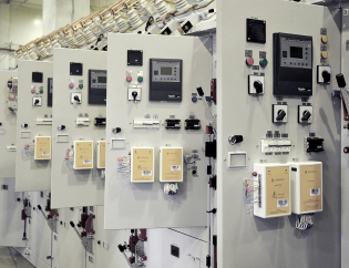
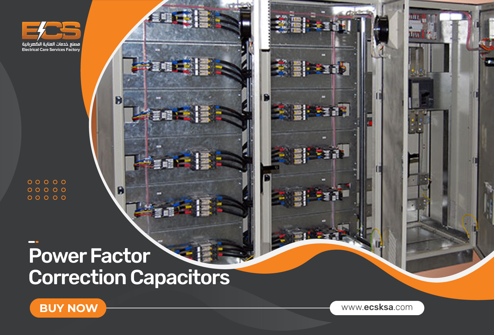 What is a Capacitor Bank?
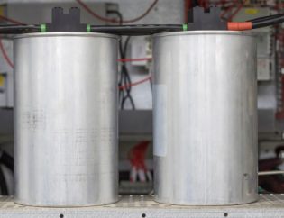
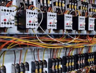
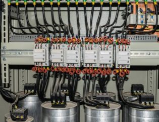
In order to gather electrical energy, many capacitors with comparable ratings are connected to one another in parallel or series to form a capacitor bank. In order to offset or correct a power factor lag or phase shift in an AC power supply, the resulting bank is then applied. They can also be used in a DC power supply to boost the overall quantity of energy that is stored or the power supply’s ability to handle ripple currents.
Typically, capacitor banks are utilized to
- Correction for Power Factor
- Compensation for Reactive Power
By canceling out a significant current flow, capacitors have the reverse effect of inductive motors, which lowers your electricity bill.
Capacitor Bank Testing
Your power system’s capacitor banks play a key role in providing accurate power factor correction. Depending on where they are located, Power Factor Correction units can operate in a variety of ways. Temperature, harmonics, moisture, and time all affect how well capacitor banks compensate for the power factor. If already installed capacitor banks are not tested or maintained within a certain amount of time, they lose their ability to perform at their best. Power factor loss can occur as a result of a capacitor’s operation deteriorating with time and lowering the power factor of your power system.
Types of Capacitor Bank Tests
A capacitor bank is checked using an IEEE or ANSI standard. Capacitor bank testing can be done in three different ways.
- Design Tests or Type Tests
- Production Test or Routine Tests
- Field Tests or Pre-commissioning Tests
1. Design Tests or Type Tests
When a company introduces a new power capacitor design, it must be tested to see if the new batch of capacitors complies with the standard. To ensure compliance with the standard, type testing, and design tests aren’t conducted on a single capacitor, but rather on a selection of randomly chosen capacitors.
Once these design tests are completed during the introduction of a new design, they do not need to be repeated for any additional batches of production until the design is changed. Design or type tests are typically pricey or damaging.
The type tests on the capacitor bank are as follows:
- High Voltage Impulse Withstand Test.
- Bushing Test.
- Thermal Stability Test.
- Radio Influence Voltage (RIV) Test.
- Voltage Decay Test.
- Short Circuit Discharge Test.
2. Routine Test
Production tests are another name for routine tests. To ensure the performance parameter of each capacitor unit in a production batch, these tests should be carried out.
- Short time over voltage test
- Terminal to case voltage test
- Capacitance test
- Leakage test of capacitor units
- Discharge resistor test
- Fuse capability test
3. Pre-Commissioning or Installation Test of Capacitor Bank
A few particular tests must be carried out before a capacitor bank is actually put on site to make sure the connections between each unit and the bank are correct and up to code.
Capacitance Test
To ensure that the connection of the bank is appropriate, the capacitance of the bank as a whole is measured using a sensitive capacitance meter. If the measured amount differs from the estimated value, there must be a bank connection issue that needs to be fixed. Instead of using only 10% of the rated voltage to determine the capacitance of the unit, we should use the whole rated voltage to get the capacitance of a bank. Where V is the applied voltage to the bank, I is the supply current, and ω = 377.7, which is constant quality, makes up the formula for capacitance.
High Voltage Insulation Test
NBMA CP-1 is followed when administering this test.
Read more: A complete guide on different types of capacitor banks

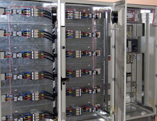
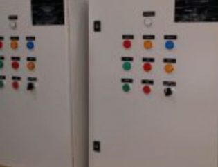
Capacitor Bank Installation
There are three different levels at which capacitor banks can be installed in a low-voltage electrical installation:
- Global installation
- Segment or group installation
- Single or individual installation
Global Installation
In this installation, on capacitor compensates for all devices in an electrical distribution system.
This solution reduces the amount of reactive power that must be placed overall, and the power factor can be kept constant by using automatic regulation, which brings the power factor close to the desired value.
This type of installation is good for:
- If you don’t want to pay for reactive energy
- If you have a small electrical system
But the disadvantages are:
- Cable losses cannot be reduced
- It is not good for large electrical systems
Segment or Group Installation
Installation of capacitors in segments is predicated on a load segment’s supply from the same switchgear being compensated. The power factor regulator, a microprocessor-based device, is typically used to control capacitor banks.
In this instance, the busbars, which power a number of loads, are connected to capacitor banks.
This system is good for:
- If you don’t want to pay for reactive energy
- If you want to reduce heat losses in your electrical distribution system
- If you want to save money on your bill
But the disadvantages are:
- You can only use this system in large electrical machines
Individual or Single Installation
Put into action by attaching a power capacitor directly to the device’s terminals that need compensating. This method reduces the burden on the electric grid by generating reactive electricity at the device terminal.
This system is good for:
- If you don’t want to pay for reactive energy
- If you want to reduce heat losses
- If you want to reduce the load on your transformer
But the disadvantages are:
- When the feeder is not in operation, the capacitor bank is not used.
- It is costly.
Capacitor Bank Maintenance Tips
When Capacitor is Disconnected
Do this every month.
- Examine the capacitors visually.
- Examine the safety fuse.
- Control the outside temperature (normally 35 °C) according to IEC 60831).
- Control the service voltage (particularly when there is little load; it should not go above +10%)
Do this twice a year.
- Keep the terminals of the capacitor clean.
- Check the condition of the operational elements’ contacts.
- Verify that there is no phase unbalance higher than 15% and that the capacitor current is not less than 25% nor more than 120% of the nominal amount by phase.
Do this once a year.
- Applying 2.5 kV for 1 second between the capacitor’s terminals and the earth will test the stiffness of the dielectric between them.
- The capacitors’ capacities at each phase should be verified.
- You might check to see if the consumption is manual as a possible indirect check.
- Verify that all terminal connections are tightly connected.
When Capacitor is Connected
- Verify that there is no need to exert force in order for the primary switch to turn on and off.
- By pushing the test button, you may determine whether the capacitor bank’s individual earth leakage prevention is functioning properly.
- Verify that the tolerance limits are not exceeded by the auxiliary control voltage.
- If the capacitor bank has an autotransformer, make sure it’s in good shape and doesn’t exhibit any signs of wear and tear.
- Make that the contactors are correctly connected and disconnected.
- Once connected, make sure the contactor is not vibrating or rattling.
- Verify how much power the capacitors are using during each phase.
- Consult the instructions for the particular regulator being used in the capacitor bank. The capacitor bank is always shipped with this manual.
- Verify that the display’s portions are functioning properly.
- Make that the keyboard is functioning properly.
- Go to Setup and verify the modified values.
- Compel a step’s manual connection and disconnection.
Conclusion
Now, you have the required knowledge for installing, maintaining, and testing capacitor banks. So, use it to your advantage. Perform the tricks to maintain your capacitor bank. It’ll reduce your electrical bill, and you’ll have a smoothly running system. Have a great day.
Do you have a question in your mind? If so, make sure to fill out the form below!