Yet, generators are controlled by specific panels that deliver the required voltage and current without any interruption.
In this article, you’ll learn everything about generator control panels. So, keep reading further to find out everything.
Generator Control Panel – What it is and How it’s Used?
Various information and parameters, including current, voltage, and frequency, are displayed on a generator control panel. Many other control panels contain meters and gauges that will display information, while some control panels have built-in screens so that operators might visually assess a generator’s function.
The control panel is often made of metal, mounted on the generator, and equipped with vibration-proof padding to protect it from shocks, whether it includes an integrated display, meter, or gauges.
Due to their size, larger commercial generators (such as industrial grade and high voltage generators) typically include control panels that are separate from the generator itself. Due to their sheer size and weight, control panels designed for these generators can typically be installed on a wall, a shelf, or as a separate unit.
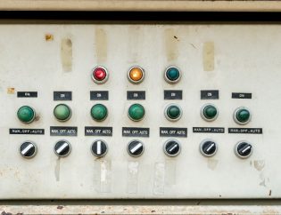
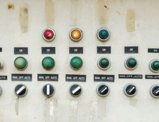
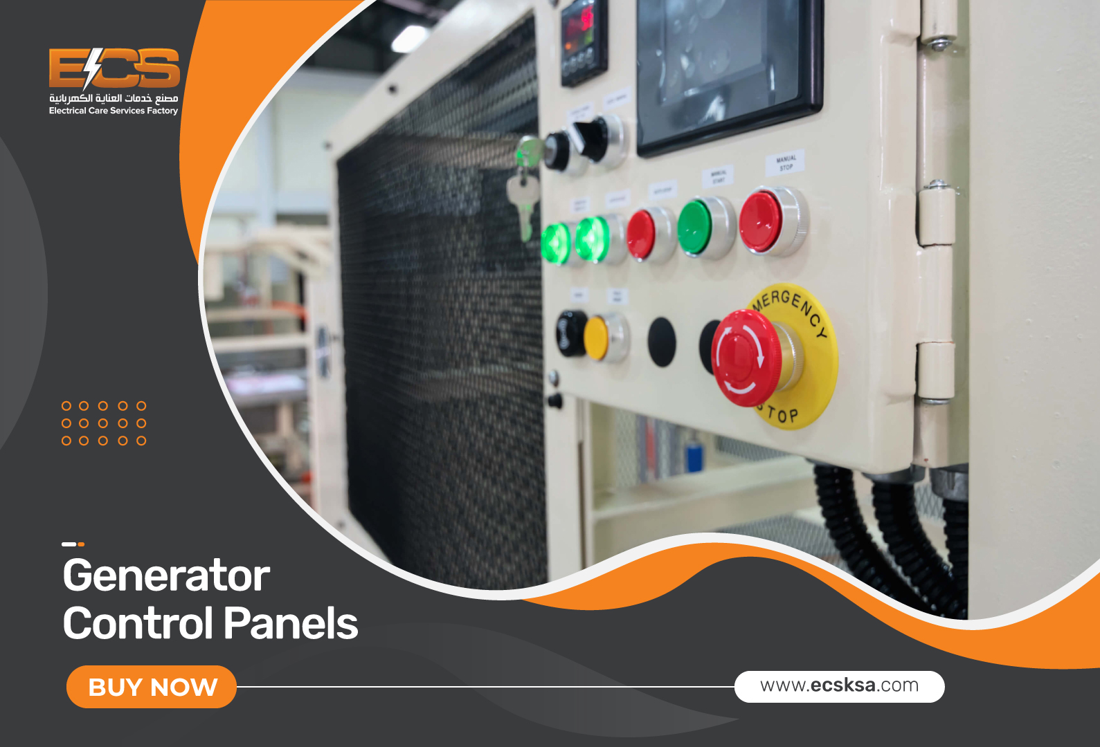
Buttons and switches on generator control panels also aid in ensuring the generator’s operation. The buttons on generator control panels, in addition to the on/off switch, enable the generator operator to set particular functions or monitor particular parameters. In general, all switches and gauges are gathered together and organized according to their functions. This makes the generator control panel user-friendly and secure for operational use, since it can reduce the likelihood that a generator operator will inadvertently press the incorrect setting during an emergency.
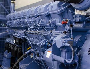
The generator control panel can be thought of as the user interface that gives operators access to the generator’s overall functions, system diagnostics, and current status. Generators are large, bulky pieces of machinery that, like all heavy machinery, are susceptible to overheating, speed variations, normal wear and tear, engine fatigue, and environmental factors like temperature and climate. Important duties include safeguarding your generator’s engine by keeping an eye on coolant temperature and oil pressure, as well as immediately shutting down the generator engine to avoid costly or irreversible damage.
How Does a Generator Control Panel Work?
Input from sensors is processed and manipulated by a microprocessor found in generator control panels, which helps the generator set monitor itself and handle any processes that arise. Temperature is a typical feedback setting. The generator might be instructed to shut down automatically to prevent damage when the engine temperature starts to meet or exceed the temperature sensor preset.
Frequently, an automatic transfer switch is combined with a generator control panel. In the event of a power loss caused by an outage, an ATS will signal the generator to start up in a matter of seconds. The generator will be instructed to turn off when the main power grid resumes operation because power will then come from there. This is simply because the ATS can detect an outage and alert the control panel to start the generator without the need to manually start the generator because it is connected to the main grid.
In the absence of an ATS (Automatic Transfer Switch), workers on-site will be required to manually turn on the generator controls in the case of a power outage and manually turn them off once power is restored. After the main grid has been restored to service, failing to turn off the generator can result in an effect called back feeding, which can be fatal to any electricians working on the electrical lines.
Main Components of Generator Set
Here are the components of a typical generator set.
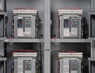
- Automatic Control Panel
- Manual Control Panel
- Transfer Panel
- Engine
- Alternator
Potential Benefits of Generator Control Panels
The advantages of using generator control panels include the following.
- Eliminating errors: A generator control panel assists in doing so.
- Efficiency gain: Your generator may operate more effectively with improved generator control.
- Enhanced safety: safer operation is supported by current and volt supervision.
- Less expense: Improved generator control will aid in reducing the frequency of generator upgrades as well as maintenance and operating expenses.
- Enhanced reliability: Monitoring generator performance and performing event analysis can provide information on how to make your generator more dependable.

How to Use and Maintain the Control Panel of Diesel Generator Set Correctly?
Distributing the electrical energy produced by the generator to the user load or electrical equipment is the primary function of the diesel generator control panel. Additionally, it serves to maintain the generator’s voltage stability under changing loads and to signal the diesel generator’s activity. A voltage setting knob, a frequency meter, an ammeter, a voltmeter, a three-phase current conversion switch, a three-phase voltage conversion switch, and other indicator lights are typically included on the control panel or controller.
According to the design specifications, some start buttons and starting locks, battery charging ammeters, water temperature gauges, oil pressure gauges, and oil temperature gauges are mounted directly on the control panel, while others are mounted on the diesel dashboard. The parts that are put inside the control panel are mostly concerned with the diesel engine’s automatic control and the excitation mode that the generator uses.
The diesel generator set’s control panel (box) has a different layout and collection of components, as well as various usage and maintenance requirements. The following is a quick explanation of how to operate and maintain the control panel using the PF13-75 control box (shown below) (box).
(A) Use of Control Panel (Box)
- To start the diesel engine, turn on the switch YK with the key and press the start button SB.
- Increase the diesel engine’s speed. The generator may produce electricity on its own when the speed of the diesel engine is close to the rated value. The excitation regulator TST1’s potentiometer allows the generator voltage to be changed (or TST2). The degassing switch SA5 can be used when the diesel engine is running, and the generator is not producing electricity.
- The voltmeter V1 and changeover switch SA1 can be used to gauge the generator’s three-phase voltage.
- The “insulation monitoring” bulbs LH4 to LH6 can be used to check the generator’s insulation. The appropriate insulation monitor lamp does not glow when a specific short circuit is shorted out.
- The output (or closure) indication HL1 illuminates when the automatic air switch is activated, signifying that the device has powered the load.
- The oil temperature meter YW, the oil pressure gauge JY, the water temperature meter SW, the frequency meter Hz, and the charging current meter A all keep an eye on the diesel engine’s operation. Voltmeter V1, ammeter A, frequency table Hz, power meter W, and power factor table cos are used to monitor the generator’s operation.
- To operate the generator as a single unit, the SA3 switch should be set to “single unit,” the SA9 switch for the synchronization meter V2 should be set to “off,” and the SA7 switch for the excitation regulator should be set to the required setting. AVR1 is activated when SA7 is in position “I,” AVR2 is activated when it is in position “II,” and when SA7 is in position “I+II,” two excitation regulators control generators operate simultaneously, which is out of control. When the unit is operating a “single unit,” pressure protection ensures the unit’s dependability.
- SA3 should be set to the “parallel” position, SA9 to the “on” position, and SA7 to the “I” or “II” position, but not to the “I+II” position when the generator is operating in parallel. Not able to manage the parallel operation.
- In order for the unit to change the rate to -3% (class III power station) or -5% (class IV power station) underrated active power, the two parallel generator sets should be placed in the adjustable speed setting position. The recommended diesel engine should be matched with diesel engines without movable speed controls to make the adjustment rate as uniform as feasible.
- The reactive power regulator QT’s differential resistance for each of the two parallel-operating diesel generator sets shall be set so that the rated voltage of each diesel generator set is 3% of the rated voltage under the rated load and has a rated power factor of 0.8 (Class III Power Station) or -5%. (Class IV power station).
- The parallel operating method must be followed, and the generator sets must operate with the same phase sequence, constant voltage, and constant frequency.
- After the Genset has started, transfer the load. Load transfer is necessary when using one generator in tandem with another (or numerous generators). The diesel engine’s throttle is adjusted as part of the active power transfer. There is more work as the throttle is opened wider. The job is smaller, and the smaller the throttle. Reactive power transfer involves adjusting the excitation regulator’s excitation potentiometer to change the generator’s excitation current. Reactive power increases with increasing excitation current. The reactive power decreases with decreasing excitation current. A portion of the active power is often transferred first, followed by a portion of the reactive power, in order to complete the load transfer in stages and reach the balance (that is, the equal distribution according to the rated power ratio).
- Operation of the unit disengagement: When the total load is reduced, it is sufficient to cause a unit to disengage, the diesel engine throttle tuning potentiometer and the excitation regulator can be adjusted separately, and the active power and reactive power are reduced to zero, and then the unit is unpacked.
(B) Control panel (box) maintenance
- To avoid dust, water droplets, metal, or other material from entering the cabinet, the control panel (box) must be maintained dry, spotless, and well-ventilated while in operation.
- Conduct routine inspections and maintenance, ensuring that all parts are in excellent contact, that fasteners are secure, that electrical contacts are intact, that the insulation and coil heating is normal, and that repairs are made as soon as problems arise.
- Before usage, the insulation resistance of the necessary electrical components should be measured if it hasn’t been used in a while. The wetted components should be dried before use if it is discovered to be damp.
Conclusion
Generator control panels are necessary pieces of equipment for all operations that require generators. If you have quality generator panels, you’ll never experience problems. Get your generator control panel today from ECSKSA and ensure reliable power for your business or home.
Check out our product pages to choose the best generator panels for your building.
Frequently Asked Questions
Q1: Which type of panel can use for generator control?
Any manual or automatic panel can be used for generator control. But to maintain quality, you must use custom control panels.
Q2: What controls generator speed?
Speed governors regulate the fuel entering the turbine, so regulating the speed and torque of the generators and, consequently, their output of electricity. Additionally, speed governors are crucial because they offer security to the turbine and stop it from over speeding.
Do you have a question in your mind? If so, make sure to fill out the form below!